
Frequently Asked Questions

Here are some common engineering FAQ that you might find helpful.

These FAQs cover design assurance, FEA verification, bespoke machinery, project scoping, and engineering FAQ. If you have a specific question, contact us or submit a design review request.

Finite Element Analysis (FEA)

Ideally: a PDF drawing pack and/or a 3D model (STEP/IGES), materials, key dimensions, supports/interfaces, and the operating scenarios. If loads are unknown, we can help define reasonable load cases based on use, environment and installation constraints.

Yes, where required. Reaction loads can be provided to support baseplate, bracket, anchor and connection detailing, and to help control downstream design risk.

Yes. Many practical issues are stiffness-related (alignment, vibration susceptibility, serviceability). We typically report both stress and deflection against agreed acceptance criteria.

Where it is relevant to the decision being made, we can include modal or buckling checks (for example on slender members, long cantilevers, or where vibration is a concern).

A concise report with: design basis and assumptions, load cases and boundary conditions, results summary (stress/deflection hotspots), engineering interpretation, and recommended actions. The aim is sign-off-ready evidence, not just plots.

Design Assurance & Independent Checks

A structured independent review of the design basis, assumptions, load cases, interfaces and failure modes, producing clear findings and actions to support sign-off.

When the primary need is to validate the design basis, completeness of load cases, interfaces and practicality of the solution. FEA is often used as part of assurance, but it isn’t always required.

Yes. We can produce controlled responses that document assumptions, load cases, and verification evidence in a format suitable for external review.

A drawing pack (PDF and/or model), materials/specification, a description of operating conditions, known loads, and any constraints around installation, access or interfaces.

We align the verification approach to the applicable standard and the decision required. Where clients have specific expectations, we structure assumptions and outputs accordingly.

Engineering Fundamentals & FEA FAQs

A singularity is a location in an FEA model where the calculated stress increases without bound as the mesh is refined. It’s caused by the mathematical idealisation (e.g., point loads, perfectly sharp corners, or fully fixed edges), not necessarily by a real-world “infinite stress” condition.
In practice, you deal with singularities by applying loads over realistic areas, modelling contacts/supports more realistically, adding fillets where appropriate, and reporting stresses at engineering-relevant locations (with mesh convergence evidence).

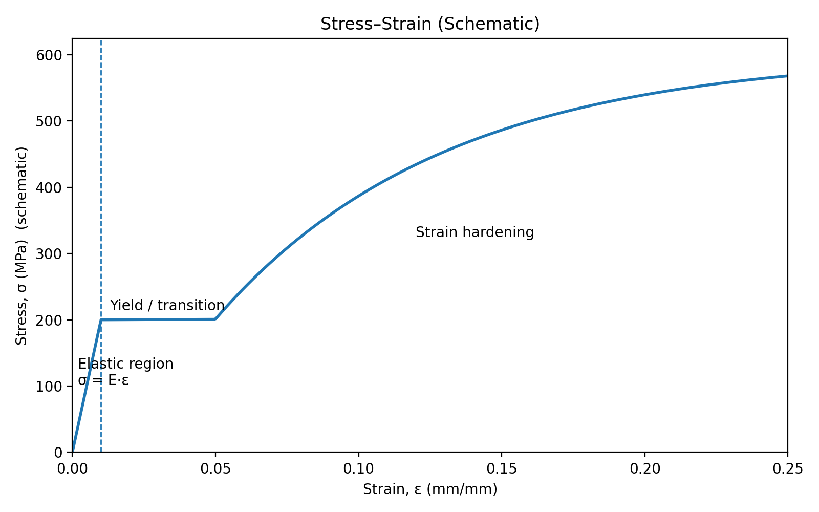
  • Stress is internal force per unit area (units: Pa, commonly MPa).

  • Strain is deformation per unit length (dimensionless, e.g., mm/mm or %).
    In linear elastic behaviour they are related by Hooke’s Law (e.g., σ = E·ε in simple uniaxial cases), where E is Young’s modulus.
Boundary conditions are how you represent the real world in the model: what is held, what is free to move, and how loads are applied.
They include constraints (fixed/pinned/roller/symmetry), applied loads (forces, pressures, torques, gravity), and contact definitions (bonded/frictional/separating). Boundary conditions often have a larger impact on results than mesh density, so they must reflect the real supports and load paths.

Linear analysis assumes:

  • small deflections (geometry doesn’t significantly change),

  • linear elastic materials (no yielding),

  • proportional response (double the load ≈ double the displacement/stress).

Nonlinear analysis is required when:

  • materials yield (plasticity),

  • deflections are large (geometric nonlinearity),

  • contact conditions change (separation/sliding/friction effects).

Von Mises stress is an “equivalent” stress mainly used for ductile metals to assess proximity to yield under multi-axial loading.
Other common outputs include: principal stresses, shear stress, displacement/deflection, strain, reactions at supports (useful for bolts and anchors), contact pressure/slip, buckling factors and mode shapes, and natural frequencies/mode shapes (modal analysis).

Mesh density controls how finely the geometry is divided into elements:

  • A coarse mesh is faster but can miss gradients and under-predict peaks.

  • A fine mesh can capture detail better but costs more time and can highlight singularities.
    Professional practice is mesh convergence: refine the mesh until the result you care about (e.g., deflection, bolt load, stress away from singularities) changes only marginally.

FEA can be very accurate, but only when the inputs are realistic:

  • correct loads and support stiffness,

  • correct material data,

  • appropriate contacts,

  • suitable mesh and convergence,

  • sensible interpretation (especially around singularities).
    Good engineering combines FEA with sanity checks (hand calcs/beam checks) and, where possible, validation against test or field evidence.

Not always — they serve different purposes.
Beam methods (SFD/BMD) can be extremely accurate when a structure behaves like an ideal beam and assumptions are valid. FEA is often better for complex geometry, non-standard supports, multiple load paths, holes/fillets, contact behaviour, and local detail. The best approach is usually both: beam theory for quick bounds and plausibility, FEA for detailed stress/deflection distribution.

Numbers like 8.8, 10.9, 12.9 are bolt property classes (strength grades).
Rule of thumb:

  • first number × 100 ≈ ultimate tensile strength (MPa)

  • second number indicates the yield ratio (yield ≈ ratio × ultimate)
    Example: 8.8 → ultimate ≈ 800 MPa, yield ≈ 0.8 × 800 = 640 MPa.
    Other markings can indicate manufacturer ID and traceability.

A tapping drill is the drill size used before cutting an internal thread with a tap. It leaves the right amount of material so the tap forms the correct thread.
Quick approximation for metric threads: tap drill ≈ major diameter − pitch (charts are used in practice to confirm the preferred drill size and thread engagement).

  • A tap cuts an internal thread (in a hole).

  • A die cuts an external thread (on a rod/shaft).

A DTI is a precision gauge used to measure very small movements. It’s commonly used for machine setup and inspection tasks such as checking runout on shafts, aligning vices/fixtures, checking flatness/parallelism, and confirming repeatable positioning. It’s a comparative instrument: it shows deviation relative to a reference.

It depends on the joint design intent:

  • Bearing-type joint: load is generally assumed to transfer through bolt shear and bearing on the hole after any initial slip.

  • Slip-critical (friction-grip) joint: the design intent is for preload and friction between plates to resist shear without slip, requiring controlled bolt preload and surface condition.
    In many everyday joints, friction helps initially but isn’t relied on unless specified as slip-critical.

  • Tensile force pulls along the axis, trying to stretch the component.

  • Shear force acts parallel to a cross-section, trying to slide one part relative to another.
    In bolts, tension relates to preload and pull-out resistance; shear relates to transverse loading trying to “cut” or slide the bolt.

Limits and fits define how two mating parts assemble by controlling tolerances:

  • Clearance fit: always has a gap

  • Transition fit: can be slight clearance or slight interference

  • Interference fit: always press-fit
    Common ISO callouts like H7/g6 specify the tolerance positions/grades for hole and shaft so the assembly behaves predictably.

Workshop, Measurement, and Commercial FAQs

Calipers are general-purpose measuring tools used to measure:

  • Outside dimensions (OD) with the outer jaws

  • Inside dimensions (ID) with the inner jaws

  • Depth with the depth rod

  • Step measurements on some models

Good technique:

  • Zero the calipers before use

  • Keep the jaws square to the feature

  • Use light, consistent pressure (don’t “spring” the jaws)

  • Avoid measuring over burrs, paint, or contamination

A vernier scale is a secondary scale that lets you read fractions of a main scale division by comparing which marks align.
Vernier calipers are manual calipers using this system (often 0.02 mm resolution), allowing accurate measurement without electronics.

A micrometer is a precision instrument that uses a calibrated screw thread to measure small dimensions very accurately (commonly to 0.01 mm or 0.001″).
Key points:

  • Use the ratchet/friction thimble for consistent measuring force

  • Check zero and calibration with a standard

  • Keep anvils clean; temperature can matter at tight tolerances

Types include outside micrometers, inside micrometers, and depth micrometers.

A bore gauge (often a dial bore gauge) measures internal diameters by comparison and is excellent for checking size, ovality and taper.

Typical method:

  1. Set a micrometer to the nominal bore size

  2. Zero the bore gauge against the micrometer

  3. Insert into the bore and gently rock it to find the minimum reading (true diameter)

  4. Read the deviation from nominal

A Torx screw has a star-shaped recess designed to reduce cam-out and transmit higher torque more reliably than Phillips/Pozi.
Common sizes are T10, T20, T30, etc. Security Torx variants include a centre pin.

Common engineering usage:

  • A bolt typically passes through clearance holes and is used with a nut. Also the thread only populates then end of the fastener.

  • A set-screw / cap screw typically threads into a tapped hole (no nut). Also the thread runs the entire length of the fastener. 

Terminology can vary (especially “set screw” in US usage), so drawings and specifications should define the intent.

Washers are used to:

  • Spread load and reduce bearing stress on the joint face

  • Protect surfaces from damage during tightening

  • Help maintain preload by reducing embedment/creep effects

  • Provide a consistent bearing surface under head/nut

  • In some cases, provide alignment or spacing (special washers)

Note: “locking” is usually better achieved with correct preload plus a suitable locking method (nyloc, thread-lock, prevailing torque nuts, etc.) rather than relying on spring washers alone.

Mechanical engineers design, verify, improve and troubleshoot mechanical systems and equipment. Typical work includes:

  • Mechanical design (CAD, materials, manufacturing methods)

  • Structural verification (hand calculations, FEA, fatigue, buckling, vibration)

  • Failure investigation and root cause analysis

  • Bespoke machinery and tooling design

  • Plant/process modifications and implementation support

  • Documentation for compliance and sign-off (e.g., technical files, substantiation packs)

In the UK, Chartered Engineer (CEng) registration typically involves:

  • Accredited academic formation (commonly an accredited MEng, or an accredited BEng(Hons) plus further learning), and

  • Initial Professional Development (IPD): developing the competence evidence in industry before applying.

Time varies by pathway and role, but many engineers reach the point of applying after several years of professional development post-university.

Tolerance analysis is the process of predicting whether parts will assemble and function correctly when each component dimension varies within its allowed tolerance.

Two common approaches:

  • Worst-case stack-up: assumes all dimensions hit their worst limits (conservative)

  • Statistical/RSS stack-up: assumes independent variation and uses probability (often more realistic for production)

It helps reduce scrap, avoid assembly issues, and ensure functional clearances and fits.

A consultant is often advantageous when you need:

  • Immediate access to senior experience without a long hiring cycle

  • Flexible resourcing for peaks in workload

  • Independent verification (useful for insurers, auditors, client-of-client approvals)

  • Specialist skills (e.g., FEA verification, failure investigation, design assurance)

  • Deliverable-based work packages with clear scope and documentation

A full-time hire is often better for continuous embedded development and long-term internal capacity building. Many companies use both.

As a rough UK benchmark, senior/principal mechanical engineers are commonly in the ~£55k–£75k bracket, with higher figures in some sectors/locations. The true cost-to-company is typically higher once employer NI, pension, holiday, software/tools, training and overhead are included.
A practical rule-of-thumb is salary × ~1.3 to 1.6 for fully loaded cost (varies by benefits and overhead).

Rates depend on seniority, risk/liability, urgency, deliverable type, and whether work is priced hourly or fixed-fee.
A common industry approach is:

  • A short scoping call to define inputs and outputs

  • A fixed price for a defined report/verification pack

  • Hourly rates used for ad-hoc support or unknown scope, often with a minimum charge

If you contact Barair, we’ll normally propose either a fixed fee (preferred for defined deliverables) or an hourly model for exploratory work.

No. For many matters (fact-finding, engineering opinion, failure investigation), clients can instruct an engineer directly.
If a report is required for court as expert evidence, it’s often arranged via solicitors because they manage procedure and instructions — but litigants-in-person can also instruct experts directly, depending on the case requirements.

CPR Part 35 governs expert evidence in civil claims (England & Wales). A Part 35 expert’s duty is to provide independent assistance to the court, not to act as an advocate for the instructing party.
In practice, a Part 35-compliant report sets out credentials, facts relied upon, assumptions, inspections/tests (if any), reasoning, conclusions, and includes the required statements regarding independence and duty.